 ___       _____ ______   ________
|\  \     |\   _ \  _   \|\  _____\
\ \  \    \ \  \\\__\ \  \ \  \__/
 \ \  \    \ \  \\|__| \  \ \   __\
  \ \  \____\ \  \    \ \  \ \  \_|
   \ \_______\ \__\    \ \__\ \__\
    \|_______|\|__|     \|__|\|__|
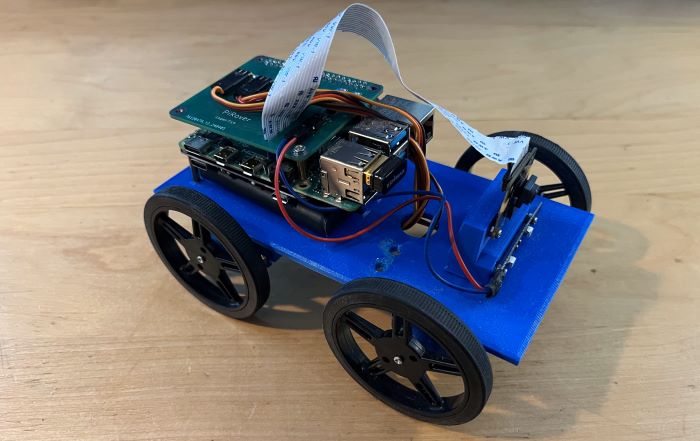
Since the remake of the "Remote Controlled Raspberry Pi Car" or "PiRover" released, I have made a few improvements and additions.
Here's an overview of the changes:
A custom circuit board replacing the temporary breadboard, which cleared up messy wiring and added space on the chasis
Completing the camera integration to the web panel
An LED strip acting as headlights for seeing in darker places, and can be togged from the web panel

The code and the parts weren't changed, so its more of an improvement rather than a complete remake like last time.
This was my first time ever designing a real circuit board, so I wasnt sure where to start. I had heard of JLCPCB, which is where I sent my final designs for manufacting, but I wasn't sure how to actually create a design.
I ended up stumbling upon Flux.ai, which was pretty straight forward to understand after reading through a few guides, and is where I created the designs sent to JLCPCB.

The board made use of a resistor and transistor to regulate voltage for the LED lights, a resistor to further reduce motor jitter, and 4 3-pin male headers for each wheel to connect through. And it sat cleanly on top of the raspberry pi as any other HAT would.
This will most likely be one of the more final changes on the physical side of the PiRover before another complete redo of the project, thanks for reading.