 ___       _____ ______   ________
|\  \     |\   _ \  _   \|\  _____\
\ \  \    \ \  \\\__\ \  \ \  \__/
 \ \  \    \ \  \\|__| \  \ \   __\
  \ \  \____\ \  \    \ \  \ \  \_|
   \ \_______\ \__\    \ \__\ \__\
    \|_______|\|__|     \|__|\|__|
You can find the KiCad files for this project on my GitHub
After my PiRover version 3 project, I have wanted to design a more complex PCB. The PCB from that project worked, and simplified the design, but it was not a very complex board that for the most part replaced a breadboard. In this project, I set out to create a more complex and dense board in order to improve my skills and learn in the process.
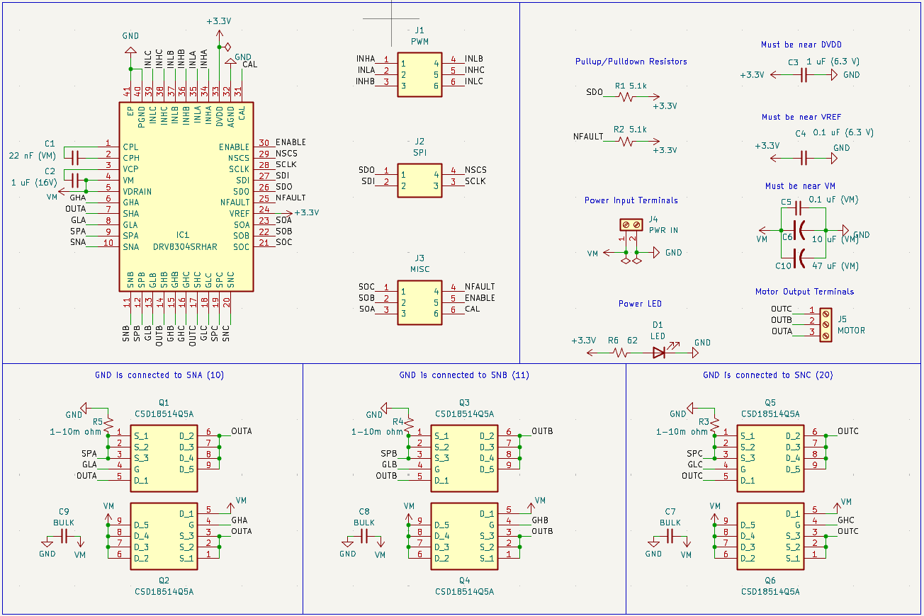
I settled on creating a BLDC(Brushless DC Motor) controller board, also known as an ESC(Electronic Speed Controller). I chose the TI drv8304 gate driver chip to be the foundation of this design, along with 6 CSD18514Q5A MOSFETs also from TI to drive the motor itself.
I based most of this design from the drv8304 datasheet provided by TI, and used KiCad to design everything. First, I started by creating the schematic, deciding what parts to connect to what pins.
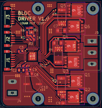
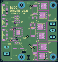
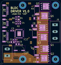
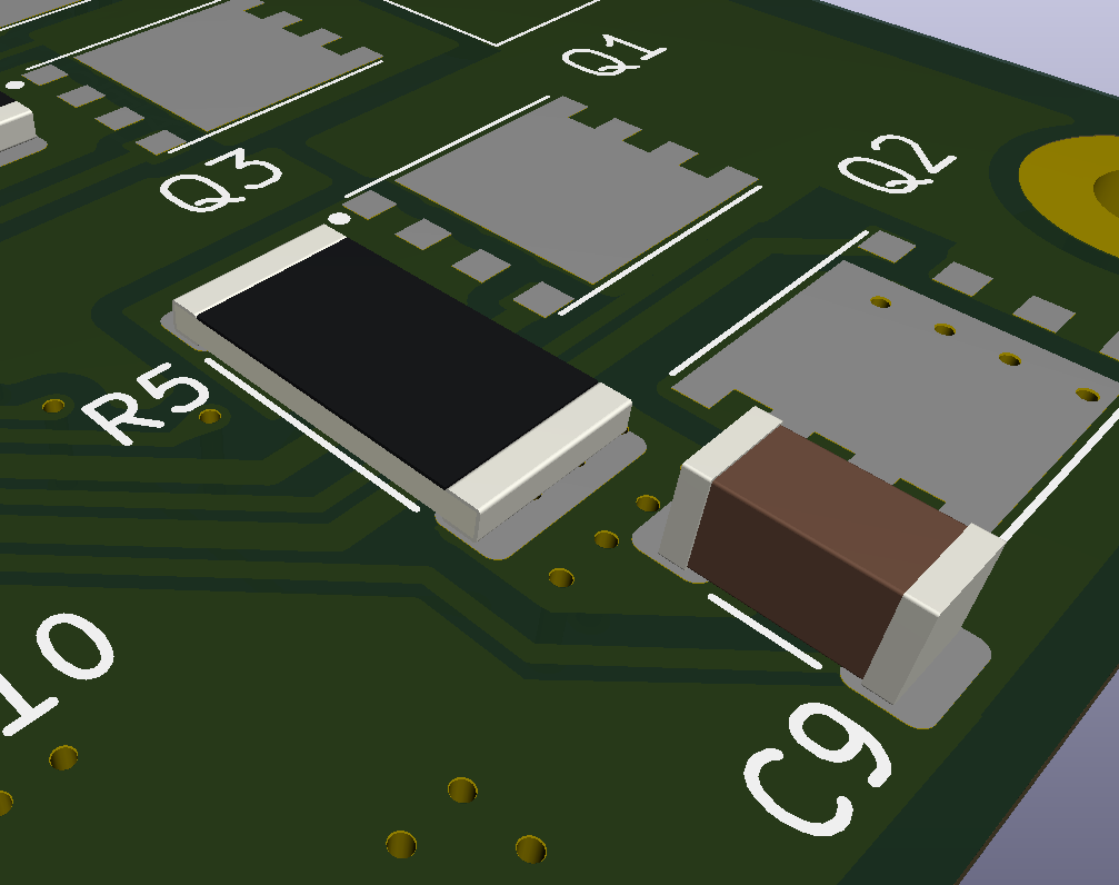
The next part of this project involved designing the layout of the board itself, choosing the size of components and laying the appropriate traces. I chose to create a 4 layer board, pictured below.

With the schematic and layout complete, I just needed to select the specific component values before ordering all of the parts. Most of these values were either standard like the main bulk capacitor (C10), but some more complex components like the shunt resistors (R3,R4,R5) required some calculations in order to choose an appropriate value.

A shunt resistor uses a very small resistance to create a measurable voltage drop that can be used to estimate the current flowing through the resistor. It uses Ohm's law in order to measure current through a simple ADC(Analog Digital Converter) on most microcontrollers.
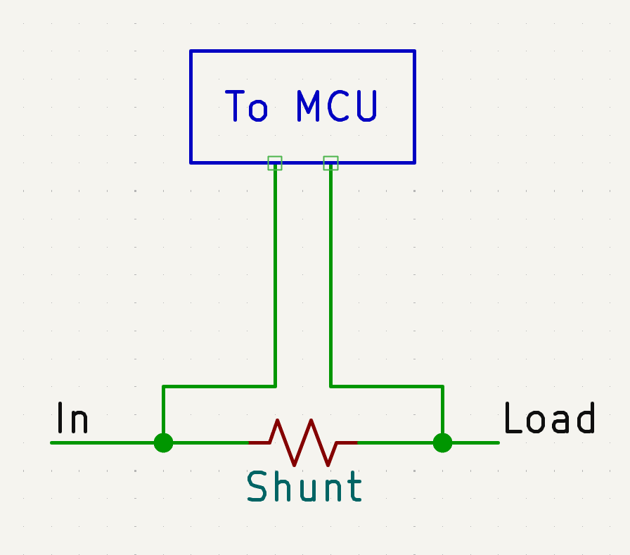
In order to determine its value, I first needed to choose a motor and find its absolute max current. In my case it was around 62 Amps. Next, I needed to choose an arbitrary gain value. This is the value that the drv8304 scales the very small incoming voltage for accurate current sensing. I selected 20 V/V as my gain and the formulas below (from the datasheet) resulted in me choosing a 1 milli ohm resistor rated at 5W!
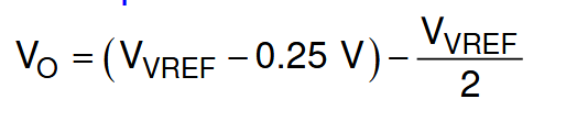
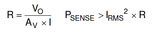
Where VREF is 3.3V, I is the max current in Amps, R is the value of the shunt resistance, Av is the gain (either 5V/V, 10V/V, 20V/V, or 40V/V). I was not able to find the Irms of my motor, nor was I able to calculate it, so I assumed 20% less than the peak current.
With my board complete and components selected, I was ready to move on, and purchased all of the parts for the assembly. I purchased the board from JLCPCB, the specific components from Digikey, and the more general components and tools from Amazon. Currently, I'm still waiting for those parts to come in, so I'll update this with my results when it's complete!